Structures & forces
Engineering Science · National 5 · mrkellydt.co.uk
What you're learning in this topic
Learning intention WALT
We are learning about structures & forces, specifically to:
know
- tension and compression and types of load
be able to
- draw free body diagrams and apply the conditions of equilibrium
- use the principle of moments to find reaction forces
Success criteria WILF
- I can identify tension and compression and types of load
- I can draw free body diagrams and apply the conditions of equilibrium
- I can use the principle of moments to find reaction forces
Forces in structures
- Tension pulls a member (it would stretch); a member in tension is a tie.
- Compression pushes a member (it would squash); a member in compression is a strut.
- When showing the forces acting on a member: arrows pointing towards each other (pushing in) show compression; arrows pointing away from each other (pulling apart) show tension.
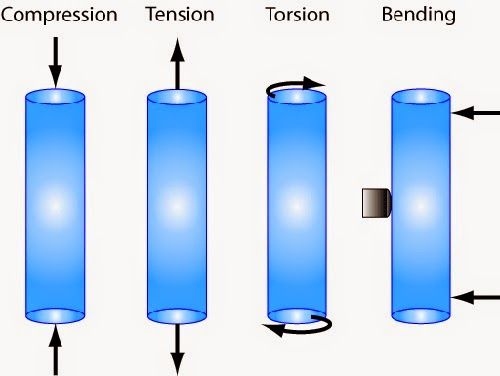
Equilibrium and free body diagrams
A structure is in equilibrium when it isn't moving: the forces balance. A free body diagram shows one object with all the forces acting on it. Three concurrent forces (acting through one point) in equilibrium form a closed triangle of forces when drawn to scale head to tail.
Triangle of forces by scale drawing
For three concurrent forces in equilibrium, a scale drawing finds two unknown forces when you know one force and the directions of the other two.
- Choose a large scale, e.g. 10 mm = 200 N. A bigger scale is more accurate.
- Draw the known force first, in its direction and to scale.
- From one end draw a line parallel to the first unknown force; from the other end, a line parallel to the second.
- Where the lines cross closes the triangle. Measure each side and convert using the scale.
- The arrows follow each other round the triangle. Use them to decide whether each member is a strut or a tie.
To find the resultant of two forces, draw them to scale and complete the parallelogram: the diagonal is the resultant. The equilibrant is the same size as the resultant but acts in the opposite direction.
Frames are made of triangles because a triangle can't change shape under load (triangulation), so it stays rigid.
Moments
- Moment = force × perpendicular distance from the pivot (N m).
- Principle of moments: for equilibrium, the sum of clockwise moments = the sum of anticlockwise moments (ΣCWM = ΣACWM).
- Also, for equilibrium, upward forces = downward forces (ΣFv = 0).
Simply supported beam: take moments about one support to find the other reaction, then use ΣFv = 0 for the first. E.g. loads 650 N at 0.8 m and 890 N at 3 m balanced by 560 N at distance d: 520 + 2670 = 560 d, d = 5.7 m.
Balance beams and parallel forces
- Concurrent forces act through one point. Non-concurrent forces don't, so they can turn an object. Parallel forces, such as loads on a beam, are non-concurrent: use moments.
- For equilibrium: upward forces = downward forces, leftward = rightward, and clockwise moments = anticlockwise moments.
- Balance beam (a pivot in the middle, like a see-saw): a 400 N child sits 1.5 m left of the pivot. Where must a 600 N child sit? ACWM = 400 × 1.5 = 600 N m, so 600 × d = 600 and d = 1.0 m to the right. The pivot pushes up with 400 + 600 = 1000 N.
Interactive simulation: try this on the revision site, where you can change the values and see the result.
Weight and loads
Loads are often given as a mass. Convert to a force first: weight = m × g = m × 9.8. A 95 kg person: 95 × 9.8 = 931 N; a 500 kg container: 4900 N. Then draw the free body diagram with every force, reaction and distance before taking moments.
Design challenge: footbridge
The brief. A council in the Borders is building a 6 m footbridge over a burn. A 900 N person stands 2 m from support A, and a 400 N bike is 5 m from A.
- Draw a free body diagram of the bridge.
- Calculate the reaction at support B by taking moments about A.
- Calculate the reaction at support A.
- State whether each member of a supporting truss would be in tension or compression and how you would find out.
What a good answer includes
- Beam with two downward loads and two upward reactions, all labelled.
- RB × 6 = (900 × 2) + (400 × 5) = 3800 → RB = 633 N.
- RA = 900 + 400 − 633 = 667 N.
- Members being stretched are in tension, members being squashed are in compression; test with a model or a simulation.
Key terms
| Equilibrant | Equal in size and opposite in direction to the resultant. |
|---|---|
| Non-concurrent forces | Forces that don't act through one point, so they can cause turning. |
| Triangulation | Triangles make a frame rigid. |
| Tie | A member in tension. |
| Strut | A member in compression. |
| Moment | Force × perpendicular distance from the pivot. |
| Principle of moments | Sum of clockwise moments = sum of anticlockwise moments. |
| Vertical equilibrium | Upward forces = downward forces (ΣFv = 0). |
| Free body diagram | One object shown with all the forces acting on it. |
| Concurrent forces | Forces acting through a single point. |
Quick check
1. In a triangle of forces, you should draw first…
- The known force
- The longest force
- The tie
- The resultant
Show answer
2. A 400 N load sits 1.5 m from a balance beam pivot. A 600 N load balances it at…
- 0.9 m
- 1.0 m
- 1.5 m
- 2.25 m
Show answer
3. Why are frames made from triangles?
- Triangles use less paint and material
- Triangles let the joints move freely
- A triangle can't change shape under load
- No force passes through a triangle
Show answer
4. A member being squashed is a…
- Strut
- Tie
- Beam
- Cable
Show answer
5. A 200 N force acts 0.5 m from a pivot. The moment is…
- 400 N m
- 100 N m
- 200.5 N m
- 0.0025 N m
Show answer
6. For a beam in equilibrium, which is true?
- CWM > ACWM
- Upward > downward
- CWM = ACWM
- No forces act
Show answer
7. Loads of 650 N and 890 N are supported by RA and a 560 N force. RA is…
- 330 N
- 1540 N
- 560 N
- 980 N
Show answer
Printable worksheet
An I do, we do, you do worksheet for this topic, with a separate answer sheet.