Structures & forces
Engineering Science · Higher · mrkellydt.co.uk
What you're learning in this topic
Learning intention WALT
We are learning about structures & forces, specifically to:
know
- tension and compression and types of load
be able to
- draw free body diagrams and apply the conditions of equilibrium
- use the principle of moments to find reaction forces
- resolve concurrent forces into components and find resultants
- find forces in frame members by nodal analysis
- work with uniformly distributed loads
Success criteria WILF
- I can identify tension and compression and types of load
- I can draw free body diagrams and apply the conditions of equilibrium
- I can use the principle of moments to find reaction forces
- I can resolve concurrent forces into components and find resultants
- I can find forces in frame members by nodal analysis
- I can work with uniformly distributed loads
Forces in structures
- Tension pulls a member (it would stretch); a member in tension is a tie.
- Compression pushes a member (it would squash); a member in compression is a strut.
- When showing the forces acting on a member: arrows pointing towards each other (pushing in) show compression; arrows pointing away from each other (pulling apart) show tension.
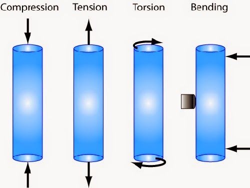
Equilibrium and free body diagrams
A structure is in equilibrium when it isn't moving: the forces balance. A free body diagram shows one object with all the forces acting on it. Three concurrent forces (acting through one point) in equilibrium form a closed triangle of forces when drawn to scale head to tail.
Triangle of forces by scale drawing
For three concurrent forces in equilibrium, a scale drawing finds two unknown forces when you know one force and the directions of the other two.
- Choose a large scale, e.g. 10 mm = 200 N. A bigger scale is more accurate.
- Draw the known force first, in its direction and to scale.
- From one end draw a line parallel to the first unknown force; from the other end, a line parallel to the second.
- Where the lines cross closes the triangle. Measure each side and convert using the scale.
- The arrows follow each other round the triangle. Use them to decide whether each member is a strut or a tie.
To find the resultant of two forces, draw them to scale and complete the parallelogram: the diagonal is the resultant. The equilibrant is the same size as the resultant but acts in the opposite direction.
Frames are made of triangles because a triangle can't change shape under load (triangulation), so it stays rigid.
Moments
- Moment = force × perpendicular distance from the pivot (N m).
- Principle of moments: for equilibrium, the sum of clockwise moments = the sum of anticlockwise moments (ΣCWM = ΣACWM).
- Also, for equilibrium, upward forces = downward forces (ΣFv = 0).
Simply supported beam: take moments about one support to find the other reaction, then use ΣFv = 0 for the first. E.g. loads 650 N at 0.8 m and 890 N at 3 m balanced by 560 N at distance d: 520 + 2670 = 560 d, d = 5.7 m.
Balance beams and parallel forces
- Concurrent forces act through one point. Non-concurrent forces don't, so they can turn an object. Parallel forces, such as loads on a beam, are non-concurrent: use moments.
- For equilibrium: upward forces = downward forces, leftward = rightward, and clockwise moments = anticlockwise moments.
- Balance beam (a pivot in the middle, like a see-saw): a 400 N child sits 1.5 m left of the pivot. Where must a 600 N child sit? ACWM = 400 × 1.5 = 600 N m, so 600 × d = 600 and d = 1.0 m to the right. The pivot pushes up with 400 + 600 = 1000 N.
Interactive simulation: try this on the revision site, where you can change the values and see the result.
Weight and loads
Loads are often given as a mass. Convert to a force first: weight = m × g = m × 9.8. A 95 kg person: 95 × 9.8 = 931 N; a 500 kg container: 4900 N. Then draw the free body diagram with every force, reaction and distance before taking moments.
Design challenge: footbridge
The brief. A council in the Borders is building a 6 m footbridge over a burn. A 900 N person stands 2 m from support A, and a 400 N bike is 5 m from A.
- Draw a free body diagram of the bridge.
- Calculate the reaction at support B by taking moments about A.
- Calculate the reaction at support A.
- State whether each member of a supporting truss would be in tension or compression and how you would find out.
What a good answer includes
- Beam with two downward loads and two upward reactions, all labelled.
- RB × 6 = (900 × 2) + (400 × 5) = 3800 → RB = 633 N.
- RA = 900 + 400 − 633 = 667 N.
- Members being stretched are in tension, members being squashed are in compression; test with a model or a simulation.
Resolving forces HIGHER
- Split an angled force into components: horizontal F cos θ, vertical F sin θ (θ measured from the horizontal).
- For equilibrium: ΣFH = 0 and ΣFV = 0. The resultant R = √(FH² + FV²) at angle tan⁻¹(FV/FH); the equilibrant is equal and opposite to the resultant.
- A uniformly distributed load (UDL) is replaced by a point load (load per metre × length) at the centre of the length it covers.
- Angled loads on beams: only the component at 90° to the beam creates a moment about the support (e.g. 3.8 sin 62).
- A hinge (pin) support can have horizontal and vertical reactions; a roller support has only a reaction at 90° to its surface.
Polygon of forces HIGHER
With more than three concurrent forces, draw them head to tail to scale: the line that closes the polygon is the equilibrant, and the resultant is equal and opposite. The quicker exam method is to resolve every force.
Example: 50 N at 0°, 80 N at 90° and 40 N at 210° (angles from the positive horizontal).
- ΣFH = 50 + 0 + 40 cos 210° = 50 − 34.6 = 15.4 N
- ΣFV = 0 + 80 + 40 sin 210° = 80 − 20 = 60.0 N
- R = √(15.4² + 60.0²) = 61.9 N at tan−1(60.0 ÷ 15.4) = 75.6° above the horizontal.
- The equilibrant is 61.9 N acting in the opposite direction (255.6°).
Structures can be mass structures (dams, walls), frame structures (bridges, pylons) or shell structures (car bodies, domes).
Nodal analysis of frames HIGHER
Start at a node with no more than two unknown members. Resolve vertically and horizontally to find each member force, then move to the next node. State the size and the nature of each force: strut (compression) or tie (tension). E.g. at node A with a 47 kN reaction: AB = 47 ÷ sin 60 = 54 kN (strut); AE = 54 cos 60 = 27 kN (tie).
Key terms
| Equilibrant | Equal in size and opposite in direction to the resultant. |
|---|---|
| Non-concurrent forces | Forces that don't act through one point, so they can cause turning. |
| Triangulation | Triangles make a frame rigid. |
| Polygon of forces | More than three forces head to tail; the closing side is the equilibrant. |
| Tie | A member in tension. |
| Strut | A member in compression. |
| Moment | Force × perpendicular distance from the pivot. |
| Principle of moments | Sum of clockwise moments = sum of anticlockwise moments. |
| Vertical equilibrium | Upward forces = downward forces (ΣFv = 0). |
| Free body diagram | One object shown with all the forces acting on it. |
| Concurrent forces | Forces acting through a single point. |
| UDL | Replace with a point load (w × length) at the centre of its length. |
| Resultant | R = √(FH² + FV²); angle = tan⁻¹(FV/FH). |
| Equilibrant | Equal and opposite to the resultant. |
| Roller support | Reaction only at 90° to the surface. |
Quick check
1. In a triangle of forces, you should draw first…
- The known force
- The longest force
- The tie
- The resultant
Show answer
2. A 400 N load sits 1.5 m from a balance beam pivot. A 600 N load balances it at…
- 0.9 m
- 1.0 m
- 1.5 m
- 2.25 m
Show answer
3. Why are frames made from triangles?
- Triangles use less paint and material
- Triangles let the joints move freely
- A triangle can't change shape under load
- No force passes through a triangle
Show answer
4. Forces 50 N at 0°, 80 N at 90° and 40 N at 210°: the resultant is about…
- 40 N
- 170 N
- 90 N
- 62 N
Show answer
5. A member being squashed is a…
- Strut
- Tie
- Beam
- Cable
Show answer
6. A 200 N force acts 0.5 m from a pivot. The moment is…
- 400 N m
- 100 N m
- 200.5 N m
- 0.0025 N m
Show answer
7. For a beam in equilibrium, which is true?
- CWM > ACWM
- Upward > downward
- CWM = ACWM
- No forces act
Show answer
8. Loads of 650 N and 890 N are supported by RA and a 560 N force. RA is…
- 330 N
- 1540 N
- 560 N
- 980 N
Show answer
Printable worksheet
An I do, we do, you do worksheet for this topic, with a separate answer sheet.