Voltage dividers & sensors
Engineering Science · National 5 · mrkellydt.co.uk
What you're learning in this topic
Learning intention WALT
We are learning about voltage dividers & sensors, specifically to:
understand
- how a sensing circuit works using LDR or thermistor resistance and Vout
be able to
- calculate the voltages in a voltage divider
- rearrange the voltage divider formula to find a resistor value
Success criteria WILF
- I can calculate the voltages in a voltage divider
- I can rearrange the voltage divider formula to find a resistor value
- I can describe how a sensing circuit works using LDR or thermistor resistance and Vout
How a voltage divider works
Two resistances in series across a supply share the voltage in proportion to their resistance: the bigger resistance gets the bigger share.
- V1 / V2 = R1 / R2
- V2 = Vs × R2 ÷ (R1 + R2)
- V1 + V2 = Vs.
Replace one resistor with an LDR or thermistor and the output voltage changes with light or temperature: this is the input signal for a control circuit. Put the sensor at the bottom to make Vout rise when its resistance rises (e.g. LDR at the bottom: Vout rises as it gets darker). Swap them to reverse the action.
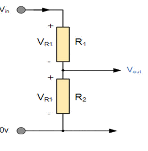
Interactive simulation: try this on the revision site, where you can change the values and see the result.
Designing a divider
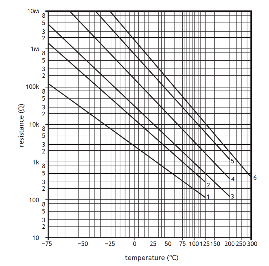
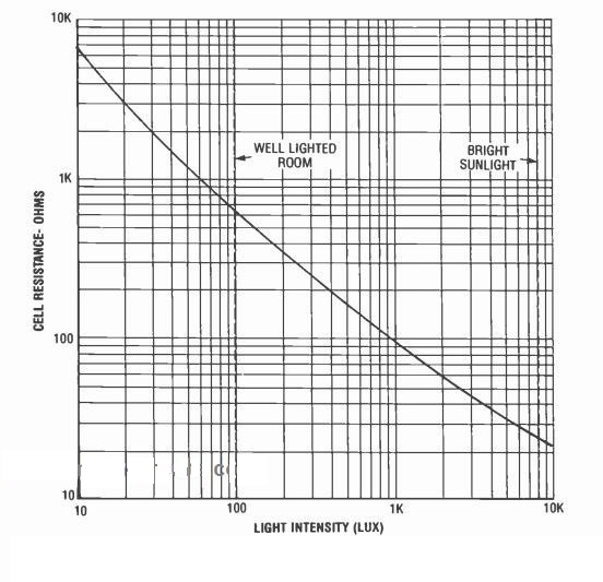
Example: a thermistor of 4.8 kΩ is at the bottom and the transistor needs 1.4 V across the top resistor on a 5 V supply. Vtherm = 5 − 1.4 = 3.6 V; R1/4.8 k = 1.4/3.6, so R1 = 1.9 kΩ. Read sensor resistances from the characteristic graph (resistance against light or temperature) carefully, including the kΩ scale.
Worked examples: voltage dividers
1. Find Vout. R1 = 4.7 kΩ (top) and R2 = 2.2 kΩ (bottom) on a 6 V supply. Vout across R2 = 6 × 2.2 ÷ (4.7 + 2.2) = 6 × 2.2 ÷ 6.9 = 1.91 V.
2. Using the ratio. If V1 = 4 V and V2 = 2 V with R2 = 5 kΩ, then V1 ÷ V2 = R1 ÷ R2 → R1 = 5 × 4 ÷ 2 = 10 kΩ.
3. Thermistor reading. A thermistor (bottom) is 3.3 kΩ at 25 °C and 1.2 kΩ at 60 °C, with a 4.7 kΩ resistor at the top and a 5 V supply.
- 25 °C: Vout = 5 × 3.3 ÷ (4.7 + 3.3) = 2.06 V
- 60 °C: Vout = 5 × 1.2 ÷ (4.7 + 1.2) = 1.02 V
- As the temperature rises the thermistor's resistance falls, so Vout falls. To make an output switch on when it gets hot, put the thermistor at the top instead.
4. Choosing a resistor (design). An LDR at the bottom is 15 kΩ at dusk. The transistor must switch on (0.7 V) at dusk with a 9 V supply. 0.7 = 9 × 15 ÷ (R + 15) → R + 15 = 135 ÷ 0.7 = 192.9 → R ≈ 178 kΩ. Choose a variable resistor so the switching point can be adjusted.
Describing a sensing circuit
A full description follows the chain: sensor resistance changes → Vin changes → transistor switches on/off → relay/output switches. E.g. "As the water heats up the thermistor's resistance falls, so Vin rises; the transistor switches on, the relay activates, the blue LED turns off and the red LED turns on." The 2024 report: some didn't refer to the thermistor resistance or Vout.
Adjusting the sensitivity
Replace the fixed resistor with a variable resistor and the circuit can be set to switch at a different light level or temperature: for example an outside light that comes on at dusk in summer and in winter. Changing the variable resistor changes how much of the supply the sensor gets, so it changes the level at which Vout reaches the transistor's switch-on voltage.
Example: an LDR at the bottom of a divider on 9 V, and the transistor must switch on (0.7 V) when the LDR is 2 kΩ. V1 = 9 − 0.7 = 8.3 V, so R1 = 2000 × 8.3 ÷ 0.7 = 23.7 kΩ: set the variable resistor to about 24 kΩ.
To make the circuit work the opposite way (on when light, or on when hot), swap the sensor and the variable resistor.
Design challenge: frost warning
The brief. A Fife farm wants a buzzer to sound when the temperature in a polytunnel drops towards freezing.
- Choose the sensor and its position in the voltage divider.
- Explain how the circuit operates as it gets colder.
- State how the switching temperature could be adjusted.
- Suggest one way to test the circuit without waiting for a frost.
What a good answer includes
- Put the thermistor at the bottom of the divider: as it gets colder its resistance increases, so Vout across it increases.
- Colder → thermistor resistance increases → Vout increases → at 0.7 V the transistor switches on → buzzer sounds.
- Replace the fixed resistor with a variable resistor.
- Cool the thermistor with ice or a freezer spray, or simulate it first.
Key terms
| Voltage divider rule | V1/V2 = R1/R2 |
|---|---|
| V out of a divider | V2 = Vs × R2 ÷ (R1 + R2) |
| Sensor at the bottom of a divider | Vout rises when the sensor's resistance rises. |
| LDR at the bottom | Vout rises as it gets darker (resistance rises). |
| Describing a sensing circuit | Sensor resistance → Vin → transistor → relay → output. |
Quick check
1. Why replace the fixed resistor in a sensing divider with a variable resistor?
- To increase the supply voltage to the circuit
- To protect the LDR from too much current
- To reverse the current through the sensor
- To adjust the level at which the circuit switches
Show answer
2. An LDR (2 kΩ) is at the bottom of a 9 V divider; the transistor must switch at 0.7 V. The top resistor is about…
- 24 kΩ
- 2 kΩ
- 12 kΩ
- 0.16 kΩ
Show answer
3. In a divider, the larger resistor has…
- The smaller share of voltage
- The larger share of voltage
- No voltage
- The same voltage
Show answer
4. Vs = 9 V, R1 = 1 kΩ, R2 = 2 kΩ. V2 is…
- 3 V
- 4.5 V
- 6 V
- 9 V
Show answer
5. A thermistor is at the bottom of a divider. As temperature rises, Vout…
- Rises
- Reverses
- Stays the same
- Falls
Show answer
6. A good description of a sensing circuit starts with…
- The sensor's resistance changing
- The relay switching on the output
- The LED lighting up as a warning
- The battery supplying the voltage
Show answer
Printable worksheet
An I do, we do, you do worksheet for this topic, with a separate answer sheet.