Transistors, relays & MOSFETs
Engineering Science · Higher · mrkellydt.co.uk
What you're learning in this topic
Learning intention WALT
We are learning about transistors, relays & MOSFETs, specifically to:
understand
- how a transistor works as a switch (about 0.7 V base–emitter)
- the purpose of a relay and a protection diode
- MOSFET threshold voltage and an advantage of a MOSFET over a BJT
be able to
- calculate base current, collector current and current gain (hFE)
- use a MOSFET graph to find drain–source current
Success criteria WILF
- I can describe how a transistor works as a switch (about 0.7 V base–emitter)
- I can explain the purpose of a relay and a protection diode
- I can calculate base current, collector current and current gain (hFE)
- I can describe MOSFET threshold voltage and an advantage of a MOSFET over a BJT
- I can use a MOSFET graph to find drain–source current
Transistor as a switch
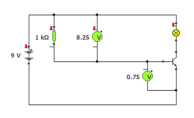
An NPN transistor has a base, collector and emitter. When the voltage at the base is about 0.7 V or more, the transistor switches on and a larger current flows from collector to emitter, operating the output (a relay, LED, buzzer or motor). A small input current controls a larger output current.
- A base resistor limits the base current to protect the transistor.
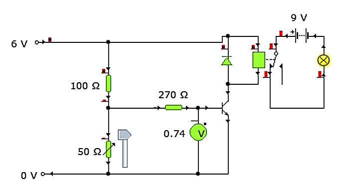
- A relay lets a low-current control circuit switch a separate, higher-current or higher-voltage output circuit.
- A protection diode across the relay coil protects the transistor from the high reverse voltage produced when the coil switches off.
The switching circuit, block by block
Almost every N5 transistor circuit has the same four blocks. Learn the chain and you can describe any of them.
- Input: a voltage divider with a sensor (LDR, thermistor or switch) and a resistor. Its output, Vout, feeds the transistor.
- Base resistor: limits the current into the base so the transistor isn't damaged.
- Transistor (NPN): when Vout reaches about 0.7 V, a small base current flows and the transistor switches on. A much larger current then flows from collector to emitter.
- Output: an LED (with its own series resistor), buzzer, lamp, motor or a relay coil, connected between the positive supply and the collector.
The three legs are the base (the control input), the collector (connected to the output device) and the emitter (connected to 0 V). The arrow on the symbol is on the emitter and points out for an NPN transistor.
Relays in more detail
A relay is an electrically operated switch. A small current through the coil makes it an electromagnet, which pulls the armature across and changes over the contacts.
- COM (common) is connected to NC (normally closed) when the coil is off, and to NO (normally open) when the coil is on.
- The two circuits are electrically separate: a 5 V transistor circuit can safely switch a 230 V heater or a 12 V motor drawing several amps.
- Use a relay when the output needs a higher current or voltage than the transistor can handle, or when the control circuit must be isolated from mains.
- Drawbacks: relays are slow, noisy and their contacts wear, so they don't suit fast switching.
Why the protection diode is needed
When the transistor switches the relay coil off, the coil's magnetic field collapses and produces a large reverse voltage (back e.m.f.). This can be many times the supply voltage and would destroy the transistor.
A diode connected across the coil, pointing towards the positive supply (reverse biased in normal use) gives this voltage a safe path to die away, protecting the transistor. In an exam answer, say what it protects (the transistor) and from what (the reverse voltage when the coil switches off).
Worked example: a light-activated lamp
Question. A garden light uses a 9 V supply. An LDR is at the top of a voltage divider and a 10 kΩ resistor at the bottom. In daylight the LDR is 1 kΩ; in the dark it is 90 kΩ. Show whether the transistor is on in each case, and describe how the circuit operates.
Daylight: Vout = Vs × Rbottom ÷ (Rtop + Rbottom) = 9 × 10 ÷ (1 + 10) = 8.2 V. This is above 0.7 V, so the transistor is on.
Dark: Vout = 9 × 10 ÷ (90 + 10) = 0.9 V. Still above 0.7 V, so the transistor is still on. This circuit doesn't work as a night light.
Fix: swap the LDR and resistor, so the LDR is at the bottom. Dark: Vout = 9 × 90 ÷ (10 + 90) = 8.1 V (on). Daylight: Vout = 9 × 1 ÷ (10 + 1) = 0.82 V. That's close to 0.7 V, so use a larger fixed resistor (e.g. 22 kΩ gives 0.39 V, off).
Describing it: "As it gets dark, the resistance of the LDR increases, so the voltage across it (Vout) increases. When Vout reaches 0.7 V the transistor switches on, current flows through the lamp and it lights."
Design challenge: cycle shed light
The brief. Your school wants the cycle shed light to switch on automatically when it gets dark. The lamp is 230 V.
- Draw a block diagram of the control circuit.
- Explain why a relay is needed.
- Explain the purpose of the diode across the relay coil.
- Describe how the circuit operates as it gets dark.
What a good answer includes
- Divider with LDR → transistor → relay → mains lamp.
- The relay isolates the low-voltage circuit from 230 V and switches the high current the lamp needs.
- It protects the transistor from the reverse voltage when the relay coil switches off.
- Dark → LDR resistance increases → Vout increases → transistor on at 0.7 V → relay coil energised → contacts close → lamp on.
BJT current gain HIGHER
hFE = IC ÷ IB. Example: an op-amp output of 4.25 V drives a 1200 Ω base resistor. IB = (4.25 − 0.7) ÷ 1200 = 2.96 mA; with hFE = 320, IC = 0.95 A. Remember the 0.7 V dropped across the base-emitter junction, and that current flowing through a sensor may split between the base and another resistor.
BJT switching calculations step by step HIGHER
Worked example: Vin = Vcc = 9 V, Rb = 150 kΩ, RL = 470 Ω, hFE = 200.
- Vbe ≈ 0.7 V, so the voltage across Rb = 9 − 0.7 = 8.3 V.
- Ib = 8.3 ÷ 150 000 = 0.0553 mA.
- Ic = hFE × Ib = 200 × 0.0553 = 11.1 mA.
- VL = Ic × RL = 0.0111 × 470 = 5.2 V.
- Vce = Vcc − VL = 9 − 5.2 = 3.8 V.
Designing a base resistor: a 6 V, 60 mA bulb with hFE = 30 needs Ib = 60 ÷ 30 = 2 mA. On a 6 V supply Rb = (6 − 0.7) ÷ 0.002 = 2650 Ω. Choose the next value down (e.g. 2.2 kΩ) so the transistor is driven fully on.
Below about 0.6 V the transistor is off; at 0.7 V it is fully on. In between it is partly on, so an output can flicker. The base–emitter voltage stays at about 0.7 V even if the input rises, because the extra voltage is dropped across Rb.
MOSFETs HIGHER
- An n-channel enhancement-mode MOSFET is a voltage-operated switch: when the gate-source voltage VGS exceeds the threshold voltage, current flows from drain to source.
- Almost no current flows into the gate, so it doesn't load the sensing circuit; it has a very low on-resistance, so it wastes little energy as heat and can switch large currents.
- BJT vs MOSFET: a BJT is current-operated and low cost, good for small loads; a MOSFET is voltage-operated, draws negligible input current and suits high-current loads such as motors and solenoids.
- Drain-source current: IDS = voltage across the load ÷ load resistance, e.g. (6 − 5.2) ÷ 2.9.
MOSFET calculations and handling HIGHER
- The drain–source channel is in series with the load, so Vs = VDS + Vload (Kirchhoff's second law).
- The MOSFET is saturated (fully on) when VDS = VGS − VT. Its on-resistance is then very low, often under 1 Ω.
- Example: a 470 Ω load on 12 V needs 20 mA, and VT = 2.5 V. Vload = 0.020 × 470 = 9.4 V, so VDS = 12 − 9.4 = 2.6 V and the gate needs VGS = 2.6 + 2.5 = 5.1 V.
- A variable resistor in a divider can set the gate voltage at the threshold, so a sensor switches the MOSFET on.
- MOSFETs draw almost no gate current, so they are easily damaged by static electricity: handle them by the case. A MOSFET can replace a relay for high-current loads; unlike a relay it has no moving contacts, so it can switch quickly enough for PWM.
Key terms
| Vce | Vcc − VL (Kirchhoff's second law) |
|---|---|
| MOSFET saturation | VDS = VGS − VT |
| Transistor switch-on voltage | About 0.7 V at the base. |
| Base resistor | Limits base current to protect the transistor. |
| Relay | Lets a low-current circuit switch a separate high-current circuit. |
| Protection diode | Across the relay coil; protects the transistor from reverse voltage when the coil switches off. |
| Current gain | hFE = IC ÷ IB |
| MOSFET threshold voltage | The gate-source voltage at which the MOSFET starts to conduct. |
| MOSFET advantage | Voltage-operated, negligible gate current, switches large currents efficiently. |
Quick check
1. Vin = 9 V, Rb = 150 kΩ, hFE = 200. Ic is about…
- 60 mA
- 0.06 mA
- 11 mA
- 1.2 mA
Show answer
2. A MOSFET (VT = 2.5 V) has VDS = 2.6 V at saturation. VGS is…
- 0.1 V
- 2.5 V
- 2.6 V
- 5.1 V
Show answer
3. Why handle MOSFETs by the case?
- Static can damage the gate
- They get hot
- They are fragile glass
- To keep them clean
Show answer
4. An NPN transistor switches on at a base voltage of about…
- 0.07 V
- 0.7 V
- 7 V
- 70 V
Show answer
5. Why is a diode placed across a relay coil?
- To light up when the relay is on
- To increase the current through the coil
- To protect the transistor from reverse voltage
- To switch the relay on and off faster
Show answer
6. Which component lets a 5 V circuit switch a 230 V heater?
- LDR
- Buzzer
- Diode
- Relay
Show answer
7. IB = 2 mA and hFE = 150. IC is…
- 300 mA
- 75 mA
- 152 mA
- 0.3 mA
Show answer
8. A MOSFET is controlled by…
- Base current
- Gate voltage
- Collector current
- Light
Show answer
Printable worksheet
An I do, we do, you do worksheet for this topic, with a separate answer sheet.